Parametric Constraints and Temporary Geometric References for Modeling
I propose adding parametric constraints and temporary geometric references directly into Blender’s modeling workflow. These would bring CAD-like precision and control to Edit Mode while remaining integrated in Blender’s standard workflow. Users could temporarily define relationships between vertices, edges, faces, and loops, enabling accurate and efficient modeling for technical, mechanical, and creative purposes.
Key Features / Concepts:
-
Edge Constraints:
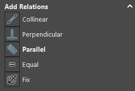
- Parallel, perpendicular, in-line/coincident, equal length to another edge.
- Optional references: other edges, faces, or global axes.
- Example: Maintain a parallel edge while moving vertices or scaling geometry.
-
Face Constraints:
- Parallel, perpendicular, coplanar/coincident, tangent (including across objects).
- Distance constraints between faces.
- Example: Keep one face tangent to a curved surface while adjusting the neighboring mesh.
-
Vertex Constraints:
- Equal spacing from edges or other vertices.
- Collinearity of 3+ vertices.
- Snap to intersections, projections, or construction guides.
- Example: Automatically align vertices to form a perfect line or radial pattern.
-
Temporary Circles / Loops:
- Treat edge and face loops as circles temporarily.
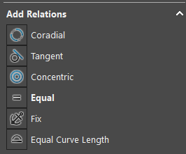
- Define radius, concentricity, or tangency to other loops/faces.
- Use as construction/reference geometry for snapping and constraints.
- Example: Fit a mechanical flange loop to a perfect circle temporarily while modeling.
-
Pattern & Array Enhancements:
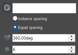
- Circular and custom arrays with equal or non-equal spacing.
- Arrays along curves, spirals, grids, honeycomb, or user-defined paths.
- Live adjustment without collapsing modifiers.
- Example: Create radial gear teeth or procedural decorative patterns with exact spacing.
-
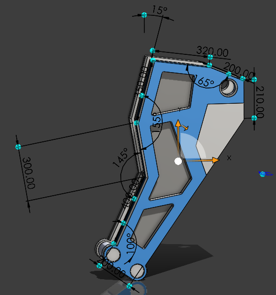
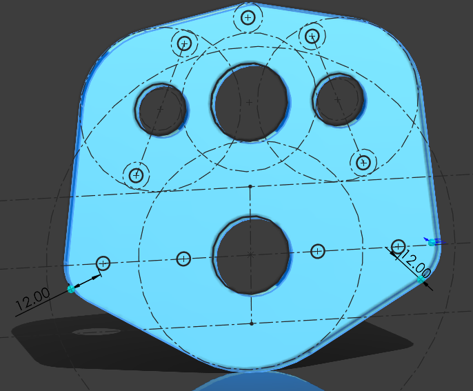
Distance & Angle Controls:
- Set exact distances: face↔face, edge↔edge, vertex↔edge, vertex↔vertex.
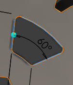
- Angle constraints: fix an edge or face at a specific angle relative to another element or axis.
- Example: Maintain precise distances between holes on a panel or angle of beveled edges.
-
Cross-Object Constraints:
- Tangency, alignment, or distance relationships between geometry in different objects.
- Example: Keep a gear tangent to a shaft while adjusting the shaft or gear geometry.
-
Reference Geometry / Construction Helpers:
- Temporary construction geometry (planes, lines, curves, points) for snapping or reference.
- Can be toggled on/off without affecting the final mesh.
- Example: Use a temporary plane to align multiple objects along an inclined surface.
-
Easy Basic Geometric Shapes:
- Quickly create primitives like rectangles, squares, pyramids, and similar shapes.
- Define width, height, and depth parameters.
- Optional: automatically make rectangle edges parallel and equal for precise modeling.
Why I Think It's Useful:
- Precision: Essential for technical or mechanical modeling without external CAD software.
- Efficiency: Reduces the need for repeated measurements, destructive edits, or manual snapping.
- Flexibility: Supports both technical (mechanical parts, architectural) and creative workflows (patterns, procedural designs).
- Integration: Unlike separate add-ons like CAD Sketcher, constraints would be native to Edit Mode, fully integrated with Blender’s modeling tools.
- Parametric Workflows: Allows live adjustments of geometry while maintaining relationships, enabling more complex and accurate designs.
Example Use Cases:
-
Mechanical Design: Model gears, flanges, or mechanical assemblies with precise alignments, tangents, and distances.
-
Pattern Creation: Generate arrays or radial patterns that maintain spacing or orientation dynamically.
-
Creative Design: Use temporary loops and constraints to create complex decorative or procedural shapes more easily.
I can get why a lot of people won't like it and think it strays too much from blender, but i think it's a very cool and useful option to have, especially for CAD users or 3D printing.
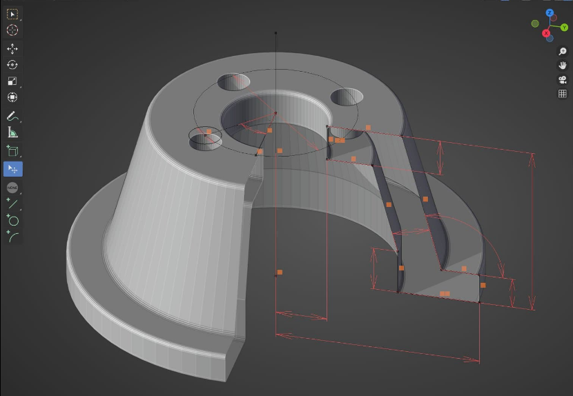
Image Examples:
0 Comments